Creating the first project
This tutorial shows how to create a basic project to help you to understand the ABStractme Tool features. It also demonstrates how to generate source code for the NetLogo simulation platform.
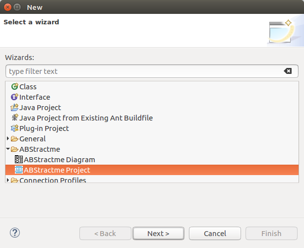
The first step is to create a new project. In Eclipse, go to File > New > Other. Select "ABStractme > ABStractme Project" as shown in Fig. 1. Click on the "Next" button.
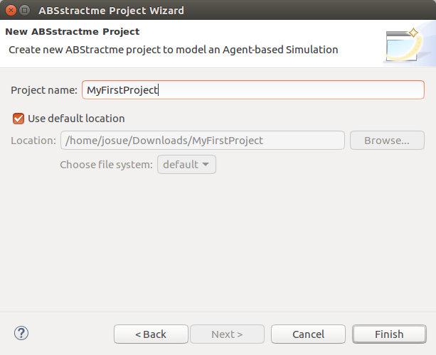
In the next window, shown on Fig. 2, specify a name for your new project and then click on the "Finish" button.
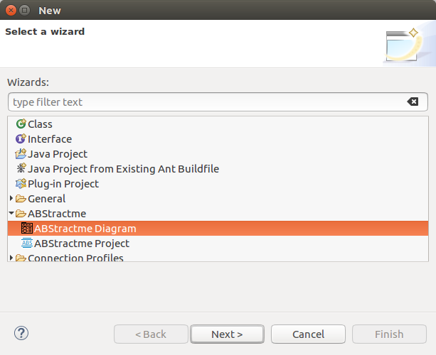
Now you must create a diagram to model the simulation. Go to File > New > Other. Select "ABStractme > ABStractme Diagram" as shown in Fig. 3. Click on the "Next" button.
In the next window, shown in Fig. 4, select the project created previously and specify a name for your new diagram. Click on the "Finish" button.
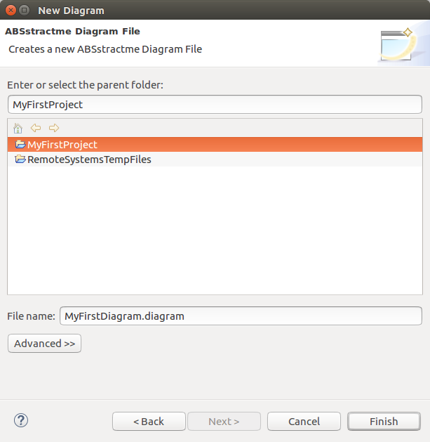
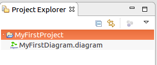
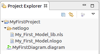
Fig. 5 shows the project structure after the diagram creation.
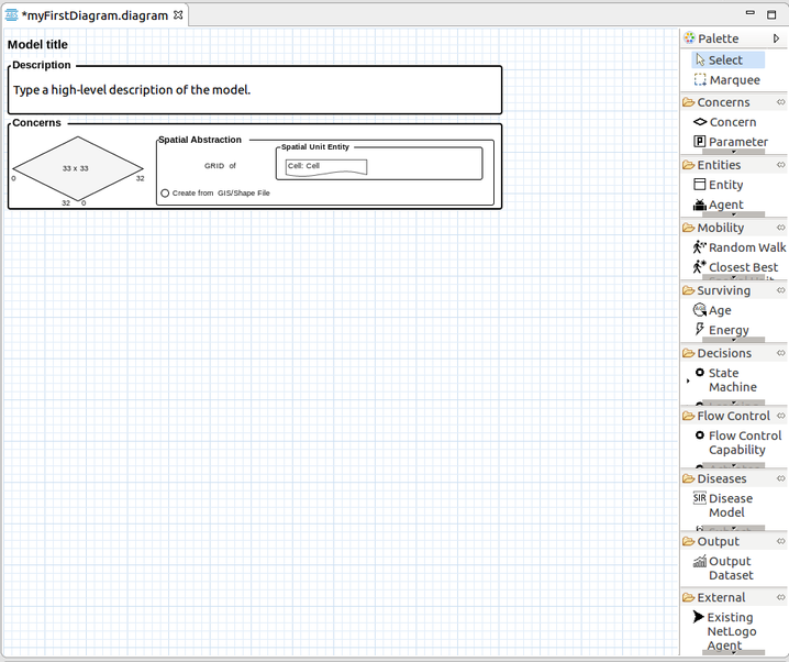
A simulation model is composed of an Overview diagram, which is shown at the center of the ABStractme modeling tool. Fig. 6 shows the overview diagram. A palette of components is show at the right side, with the available modeling constructs.
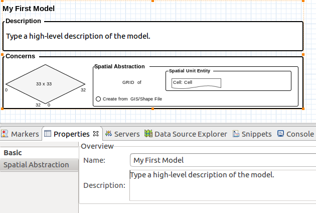
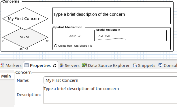
When you select the main rectangle, a Properties View (Fig. 7) shows the model details. Using this property view, you can edit the model name and description.
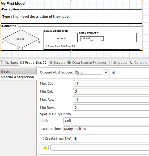
Next, we will show you how to specify a Grid environment with fixed size
In the Properties View, open the Spatial Abstraction tab and change the fields "Max Col" and "Max Row" to 49.
The numbers on the diamond located on the main rectangle of the overview diagram are changed to 50 x 50, as shown in Fig. 8
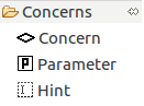
Now select the Concern element from the palette (as shown in Fig. 9) and click on the main rectangle of the overview diagram.
A concern will be added to the overview diagram.
Select the concern diamond on the main rectangle. On the properties view (Fig. 10) specify a name for the concern. You can also specify a description for the concern.
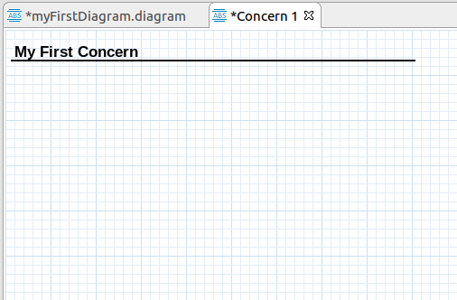
Open the Concern tab that appeared after the creation of the concern. A new window will appear with the concern diagram, as shown in Fig. 11.
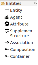
Now you can add entities to the concern, as well as agents and simulation parameters. Select an agent to add, by clicking on the Agent element on the palette, as shown in Fig. 12, and clicking anywhere on the concern diagram.
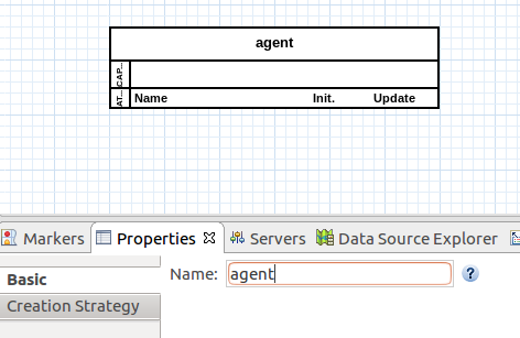
The agent box will appear on the diagram. Select the box. By using the Properties View set a name to the agent, as shown in Fig. 13.
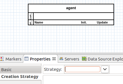
On the properties view, change to the Creation Strategy tab as shown in Fig. 14.
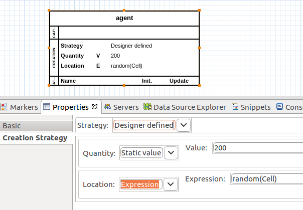
Change the field Strategy to Designer Defined. Other fields should look like Fig. 15.
In the Quantity property, set the Value field to 200 so that two hundred agents will be created when the simulation is ran.
Save the diagrams. Now you can generate NetLogo source code from the simulation model.
Generating NetLogo Source Code
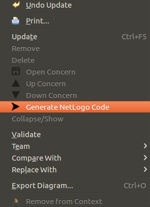
Right click on the diagram and select Generate NetLogo Code, as shown in Fig. 16.
After a while, a message window will appear showing that the source code was successfully generated.
Right click on the project folder within the Package Explorer and select Refresh.
Fig. 17 shows the generated NetLogo source files.
Before running the simulation, you must configure NetLogo following the steps available at this link: NetLogo configuration required to run the generated simulations.
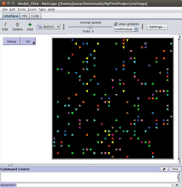
Open NetLogo and select File > Open. Select the file that ends with .nlogo. With the simulation opened, click on the "Setup" button and the simulation will appear on NetLogo as shown in Fig. 18.
The different colored dots are the two hundred agent units that were set up previously.
The complete project created on this tutorial is available to download on the link below.