Summary
An Entity is a relevant object that exists in a simulation.
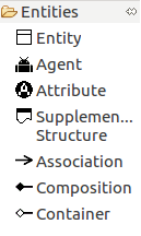
Fig. 1 shows all the objects related to the entities that can be managed on the ABStractme Tool.
Entity
Any relevant object that exists in a simulation should be represented as an entity.
An entity may have attributes and relationships. A creational strategy may be associated with an entity to describe how instances are created at the setup of the simulation.
An entity is represented by a box with the following three sections:
i) the entity name: any valid string (spaces are allowed).
ii) how it is created (creational strategies).
iii) its attributes.
Fig. 2 shows the box that represents the entity on the diagram.
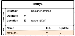
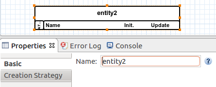
Fig. 3 shows how to define the entity name in the properties.
Creational Strategy
A creational strategy abstracts how entities (and agents) are created and located in the environment.
Each strategy requires additional elements, such as files or sources.
All creational strategies are represented in the creation section of an entity box. The first element in this creation section is the strategy type.
The following four creational strategies are supported:
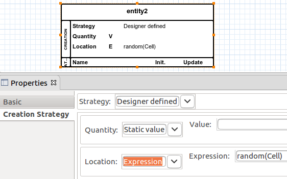
i) Designer DefinedThe designer is in charge of specifying the number of entities that are created and their locations using sources.
Only the following sources are accepted:
– Quantity: Static Value (V), Manual (only MI,MB, or MLV), Parameter (P), or Expression (E). In all these cases, the resulting value of the source must be an integer value.
– Location: Static Value (V), Manual (only MI or MLV), or Expression (E). The resulting value of the source must be the absolute position of the entity on the environment (e.g., (x,y) coordinate). For an Expression source, the result value can also be the name of another entity specified in the model. In such a case, the newly created entity will be located at the same position as one existing entity whose name was provided.
Quantity and location are shown one per line, as shown in Fig. 4.
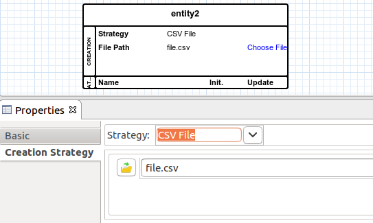
A CSV file must be provided. One entity is created for each line of the CSV file, and the comma separated fields are available for use in Expression (E) sources to initialize entity attributes.
A line with the file path is shown.
Fig. 5 shows how to associate the CSV File strategy to an entity.
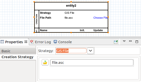
An ASCII GIS file must be provided. One entity is created for each data value, and its location is the spatial unit at that coordinate.
A line with the file path is shown.
Fig. 6 shows how to associate the GIS File strategy to an entity.
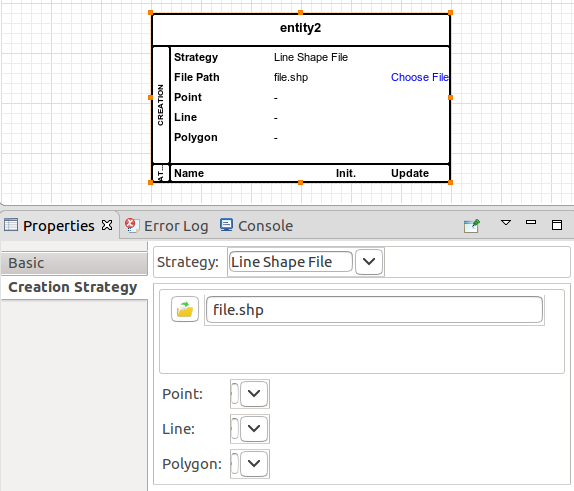
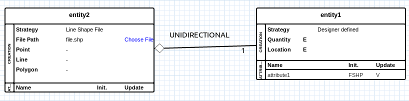
A GIS Shape file must be provided. This strategy can be only used to create an entity which is composed of one, two, or three other entities as specified using composition relationships. In such a case, one instance of the composite entity is created, and its contained entities are generated according to the mapping of points, lines, and polygons to their corresponding entity types.
A line with the file path is shown. Additional lines are included to specify the mapping of points, lines, and polygons to their corresponding entity types. At least a point mapping must be defined. Line and polygon mappings are optional.
Fig. 7 shows how to associate the Shape File strategy to an entity.
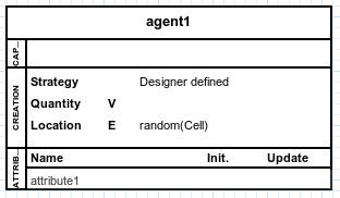
Agent
An agent is a particular kind of entity that has agent capabilities, such as decision capabilities (learning, adaptation, state machines), and behavioral capabilities.
The concrete syntax of agents extends the syntax of entities: a box with sections.
In addition to the name, creation, and attributes section, an agent box has an additional section to specify its capabilities. This capabilities section is located in between the name and creation section.
In the capabilities section, agent capabilities are enumerated.
Fig. 8 shows the box that represents the agent on the diagram.
Attribute
An entity is an abstract Type, so, it can be used to define attributes.
An attribute represents a variable value, which could be a state variable of entities and agents or a parameter of the simulation.
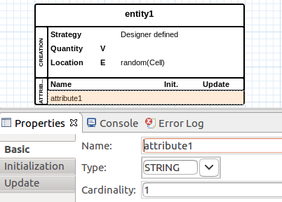
An attribute is described by its name, type, and cardinality (i.e. whether this value is a collection and of how many elements). It is associated with a value when a simulation runs.
Fig. 9 shows how to define the attribute name, type and cardinality in the properties
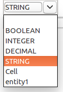
An attribute has a type, which can be a primitive type or a complex type. The following are primitive types:
STRING: text values; line breaking is not accepted.
INTEGER: integer values.
DECIMAL: decimal values.
BOOLEAN: boolean values (true/false).
Either a primitive or a complex type can be assigned to an attribute.
Fig. 10 shows the primitive and complex types available to select in the attribute properties.
If the attribute is assigned to an entity or an agent, it represents a structural feature (or, in other words, a state variable).
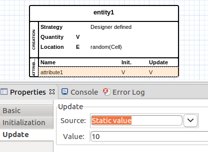
Sources can be related to an attribute, to set its initial value, or to update its value at each timestep.
Fig. 11 shows the initial value properties section.
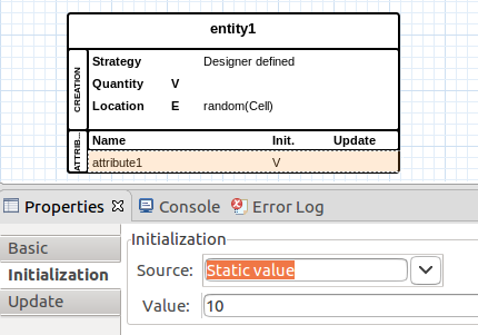
Fig. 12 shows the update value properties section.
Source
A source abstracts the provision of values, hiding low-level details of how values are provided.
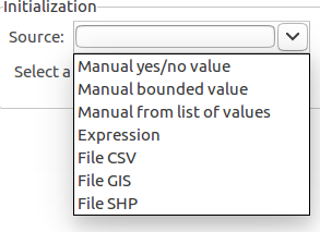
Fig. 13. and Fig. 14. show the possible sources to select in the attribute properties.
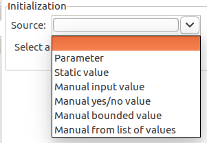
A source is represented by its identifier, the following are possible identifiers:
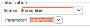
Parameter:The provided value is the value of a previously defined parameter.
Fig. 15. shows the parameter source being set in the properties section.
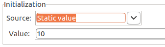
The designer informs the value directly in the specification.
Fig. 16. shows the static value being set in the properties section.
The value is provided at runtime, using some input component. The following are the supported manual sources:
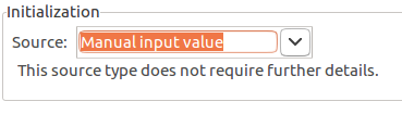
Manual Input: a manual input that accepts a string or numeric values.
Fig. 17 shows the manual input in the properties section.
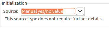
Manual Yes/No: manual yes/no input that may be used for boolean values.
Fig. 18. shows the manual yes/no input being set in the properties section.
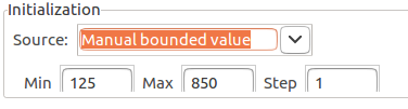
Manual Bounded: manual input of numeric values. This source creates an input component that allows numeric values bounded by a min-max interval and that are multiples of a step value. I.e., min=3, max=9, step=2 accepts the following values: 3,5,7,9.
Fig. 19 shows the manual bounded input being set in the properties section.
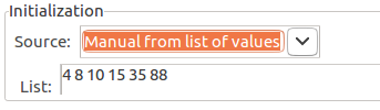
Manual from List: Manual input whose value is picked from a list of allowed values.
Fig. 20 shows the manual from a list values input being set in the properties section.
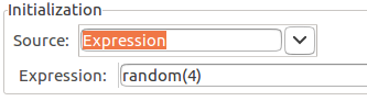
An expression specifies the operations over values or parameters that are used to compute the resulting value.
Fig. 21 shows the expression source input being set in the properties section.
The sources below read values from files. How values are interpreted depends on the element whose source is related to.
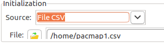
Comma Separated Values:The value is read from a CSV file.
Fig. 22 shows the CSV file source input being set in the properties section.
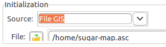
The value is read from an ASCII GIS file (.gis extension), which is a tabular data file, in which each value is associated with a point in the space.
Fig. 23 shows the GIS file source input being set in the properties section.
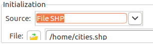
The value is read from an SHP file (.shp extension), which is a structured data file that represents points, lines or polygons in the space.
Fig. 24 shows the SHP file source input being set in the properties section.
Supplementary Structure
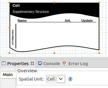
Supplementary structures are used to group related elements in the concern. They support spatial unit attributes. They are necessary when we need attributes that are common to all entities of the concern. The spatial unit must be set according to the type of the spatial unit entity that can be placed on the overview diagram.
Fig. 25 shows the box that represents the supplementary structure on the diagram.
Relationships
A relationship abstracts a relation that may exist between entities.
A relationship specifies sources and target entities.
An entity can have many relationships. The source entity owns the relationship.
A relationship also specifies its type and direction.
The cardinality of a relationship specifies how many target entities may be related to the source entity during the execution of a simulation. The semantic of the cardinality value is as follows.
-1: indicates that many (unlimited) target entities can be related to the source entity.
1: indicates that precisely one target entity can be related to the source entity.
any value > 1: indicates the number of target entities that can be related to the source entity.
0: not allowed, does not make sense.
Relationship types and their semantics are described as follows.
AssociationIndicates that the source entity is a group of entities. Such a group may have particular attributes and is created following a creational strategy. E.g., a friendship entity abstracts a group of two or more people; a traffic link entity abstracts a group of two traffic nodes.
Note: cardinality specifies the number of participants of the group and so must be greater than 2.
Fig. 26 shows an example of an Association relationship.
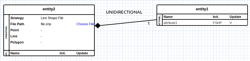
Indicates that the source entity is composed of instances of the target entity, representing a whole-part relationship.
Its semantics is related to the creation of the component entities: the whole (source) is responsible for creating the parts (targets), and the whole does not exist without its parts. For example, a traffic network is composed of traffic nodes and traffic links.
An entity who is the source of a composition relationship must specify a creational strategy that abstracts the instantiation of related entities (e.g. a shape file strategy).
Fig. 27 shows an example of a Composition relationship.
Indicates that the source entity can contain instances of the target entity.
Its semantics are related to a physical sense of containment, e.g. a relief center may contain civilians.
Fig. 28 shows an example of a Container relationship.
The semantics of relationship directions are related to the awareness of the relationship.
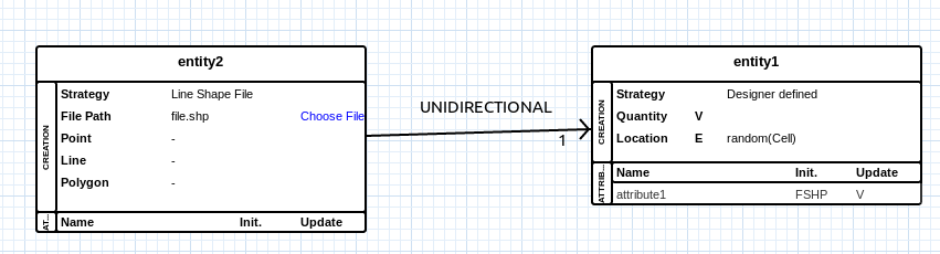
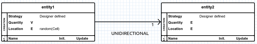
UnidirectionalOnly the source entity is aware of the relationship. Consequently, any Expression source in the source entity can refer to the target entities. Examples:
Composition between traffic network (source) and traffic link (target). The traffic network entity can specify an Expression to count the number of vehicles in all its traffic links: sum( vehicles( traffic links ) ).
Container between relief center (source) and civilian (target). The relief center entity can specify an Expression to compute the sum of the energy of civilians it contains: sum ( energy( civilians ) ).
Association between the team (source) and player (target). The team entity can specify an Expression to compute the average age of its players: avg( age( players ) ).
Fig. 29 shows an example of a unidirectional relationship.
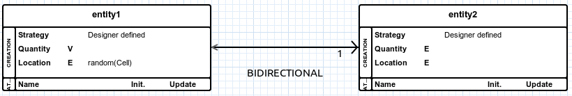
Both source and target entities are aware of the relationship. Consequently, any Expression source in the source can refer to the target, and vice-versa.
Fig. 30 shows an example of a bidirectional relationship.